Magnetic Flux
00.45
Symbol | Unit | Unit equivalent | |
| Magnetic Flux |  | Wb (weber) | V s |
| Magnetic Field (or magnetic flux density) | B | T (tesla) | Wb m-2 or V s/m² |

When placed in a magnetic field, fixed magnets (magnetic dipoles) tend to align their axes to be parallel with the magnetic field. That is why iron filings line up to show the field lines when sprinkled around a magnet. They become little tiny magnets are line up - axes parallel to the field lines from the permanent magnet.
A changing magnetic field can induce an electric field - electromagnetic induction.
Magnetic Fields are formed around moving charges (and therefore around current carrying wires - as they have a net movement of charge!).
The field lines show the direction a plotting compass would point if placed at that point in the field. They always fowm complete loops (unless they start and finish on a magnet - then the domains inside the magnetic material would complete the loop) and they NEVER cross.
Magnetic fields have an effect on moving charges at right angles to them - and only moving charges produce magnetic fields.
If the charge you are dealing with is NOT at right angles to the field you will have to find out the velocity vector that is at right angles to the field (see module 2 of the AS course).

You have to be careful you know what you are doing with this though!
The thumb points in the direction that the charged particle will experience a force towards.
The forefinger points in the direction of the field.
The second finger points in the direction of conventional current (points in the direction the charged particle is travelling IF IT IS POSITIVE!!).
If you are looking at the effect on an electron you have to have the second finger pointing in the opposite direction to its velocity...
F = qvB
where
B = the magnetic field's flux density
v = velocity of the charged particle
q = the charge on the charged particle
If a charge enters a uniform field it will therefore experience a constant force at right angles to its velocity - making it move in a circle.

F (magnetic) becomes F (centripetal)
So qvB = mv2/r
Rearranging we get that r = (mv)/(qB) = p/(qB)
This means that:
- the faster it is travelling the bigger the circles it will make
- also the bigger its mass is the bigger the radius of those circles
So, the bigger its momentum the less effect the field will have on its motion
- increase the strength of the field and you'll have more effect on its motion (smaller circles),
- increase its charge and you'll have more affect on its motion too

Click here to enlarge image
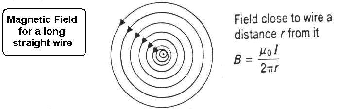
Close to the wire the circles of the field lines are virtually uniformly spaced but they do get further apart when you get further away...

Click here to enlarge image

Click here to enlarge image
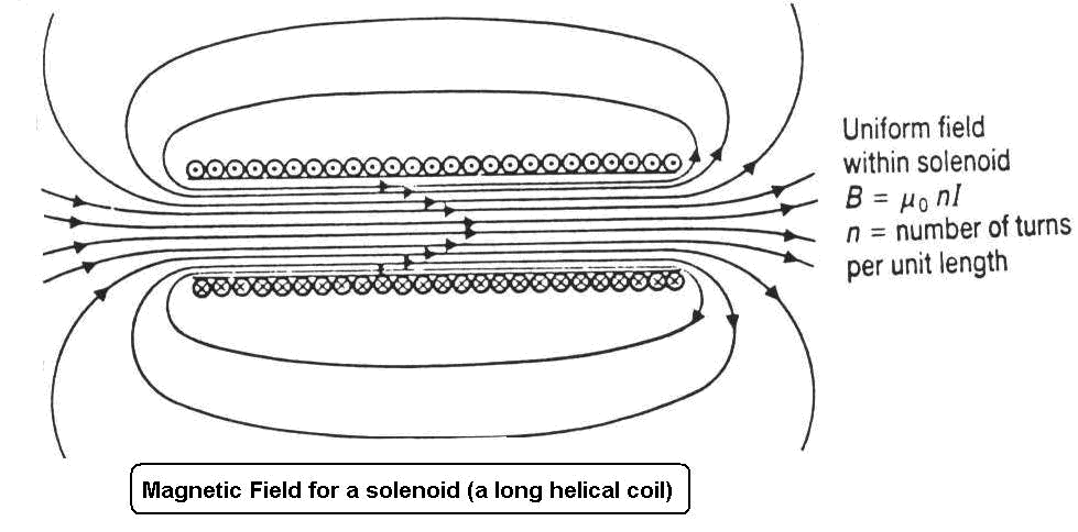
Solenoids are useful to the physicist as you can perform experiments within a uniform magnetic field and know it's value too by setting the current to give you the field you require.

Electromagnetism
00.41
Moving charges create a magnetic field. Therefore all electrical wires have a magnetic field around them (but only when the current flows). The field lines are a concentric circle pattern. The direction of the field lines can be found using the right hand grip rule. You must know this. Grip a pencil in your right hand so that your thumb points in the same direction as the pencil tip and your fingers curve around it. The pencil represents the current and its tip the direction of the current arrow. Place the pencil on the page (tip into or away from page as required) and then your fingers point in the direction of the field lines.

Symbol for a current carrying wire; a section through a current carrying wire has either the arrow tip (current coming out of the page at you) or the cross of the tail feathers of the arrow (current going into the page away from you).
NB Don't treat the circle for the edge of the wire as a field line and put an arrow on it!!

A solenoid is a long coil of wire. It's field pattern is like a bar magnet's, the only difference is that you must extend the field lines through the centre of the coil... they therefore form loops instead of starting and ending on a pole. They are virtually parallel through the centre of the coil.
See the animation of this by clicking here.
- Don't draw too many or you'll find it difficult to keep the diagram symmetrical and correct.
- Draw field lines in a different colour from the wiring.
- Ensure the circuit is complete.
- Don't forget to put in the current direction and then find out which end of the coil acts like which pole of a magnet. Mark these clearly on your diagram. .
- Finally put in the field line direction.

The solenoid acts like an electromagnet
The bigger the current, the stronger the field, the greater the number of turns, the stronger the field- (The stronger the field the closer the field lines). The presence of a soft iron core increases the strength of the field substantially.
The core must be soft otherwise when the current is switched off the core would still be magnetised.
A d.c. power source (e.g.. battery) must be used so that the current only flows in one direction. If an a.c. current (mains supply) is used the direction that current flows changes so many times in a second that the domains in the core do not have time to line up in one direction before they are pulled into the opposite direction. This results in a random arrangement of domains and a net zero magnetic field in the core.
Making an electromagnet
Uses of the electromagnet
- To pick up ferromagnetic materials in a scrap yard. Attached to a crane it is useful to pick up scrap iron and steel. There is no need for careful positioning of a hook and you simply switch the current off to drop scrap (disentangling a hook can be tedious).
- To sort ferromagnetic materials from non-magnetic materials such as aluminium in a scrap yard.
- In circuits like the electric bell.
The Transformer
00.37
 Most of the electronic devices that we use need a transformer if they are to run when they are plugged into the mains. Microchip circuitry does not need a big voltage to operate, in fact a big voltage will simply cause the chip circuitry to burn out. Such circuits run on voltages of between 5V and 12V. Therefore a transformer is necessary to 'step-down' mains voltage (230V) to this level. Any device you have that can run off batteries or via a mains connector will have a transformer incorporated into that connector. Sometimes they 'hum' and they always get warm after being switched on for a while.
 What is a transformer?
It is a laminated (made up in layers - see the photo below) soft iron core with two insulated coils of wire wrapped around it.

Click here for Faraday's early experiment
The windings of the core are made of low resistance copper. The first coil is called the primary coil. This is the coil that has the supply voltage applied across its ends. The second coil is called the secondary coil. This is the coil that has the output voltage across its ends. This is the coil that is connected to your appliance.

Why is the core laminated?
The core is not designed to have any currents induced in it. It is however a conducting loop that experiences a changing magnetic field, it will therefore have small currents induced in it - these are called 'eddy currents'. The core is laminated to reduce these to a minimum as they interfere with the efficient transfer of energy from the primary coil to the secondary one. The eddy currents cause energy to be lost from the transformer as they heat up the core. Laminated means 'made up of insulated layers of iron 'glued' together' rather than being in a single solid 'lump'. A laminated core has a higher resistance than a non-laminated one with the same number of domains. It therefore does not get such big a currents induced in it
How a transformer works
An alternating voltage (VP) is applied across the primary coil. This causes a changing magnetic field to be formed around the primary coil.
The magnetic domains inside the soft iron core line up in response to the magnetic field from the coil.
The secondary coil experiences the changing magnetic field produced by the primary and the core. It responds to this changing magnetic field by producing a voltage (VS) across its ends (an induced EMF) by electromagnetic induction.
(The key words you must mention when explaining this are in bold type)
Why must the source voltage be an alternating voltage?
Electromagnetic induction only happens when a wire loop experiences a changing magnetic field . The wire and field lines must move with respect to each other so that the wire can 'cut the lines of flux'.
How can we get a different voltage out of a transformer from the one we put in?
This is achieved by varying the ratio of the number of turns of wire on the primary and secondary coils. If there are more turns on the secondary then the output voltage will be bigger by the same ratio and vice versa.
A step-up transformer has more turns on the secondary than on the primary. It therefore produces a bigger output voltage than input voltage.
A step-down transformer has less turns on the secondary than on the primary. It therefore produces a smaller output voltage than input voltage.

Although transformers lose some of the energy input as heat (that is why the transformer gets warm), they are pretty efficient and about 99.9% of the input electrical energy is converted to output electrical energy. Therefore in examination questions at this level you can assume that the transformer is 100% efficient.
This means that:
power in = power out
power of primary = power of secondary
PP = PS
IPVP = ISVS
As the voltage is stepped up, so the current is stepped down!

In the above photograph the school transformer was used. 10.05V (rounded by the meter to 10.1V) across the primary coil of 2,000 turns resulted in an output of 100.5V across the secondary coil of 20,000 turns.
The Symbol

The symbol consists of two curled lines, representing the coils. These are unconnected, as there is no connection between the coils on a real transformer. The line (sometimes two or three are drawn) in the middle represent the magnetic link between the coils that is made by the soft iron core.
The Equation
There is a mathematical link between the number of turns and the voltages on each coil.

This ratio equation must be known for examination purposes. It doesn't matter which way up you write it, or which way round. Therefore always start with the unknown quantity in the top left position.
Example questions:
Example 1

Ns is the unknown.
We therefore have to arrange the equation as follows:

Ns / 600 = 200/20 = 10
So, Ns = 600 x 10 = 6000 (no unit as you are working out the number of turns)
In tests and examinations y ou must show your calculation in full in an examination to show that you understand how to use it.
There is a quick way to analyse this circuit and it is handy to do this as a quick check.
Look at the ratio relationship between the voltages and turns they will be the same for each.
Example 2

This time Vs is the unknown.
We therefore have to arrange the equation as follows:

Vs / 6 = 2000/50 = 40
So, Vs = 6 x 40 = 240 volts (don't forget the unit!)
Lets try the check again

Example 3

Now we have Vp as the unknown.
We therefore have to arrange the equation as follows:

Vp / 12 = 3500/100 = 35
So, Vp = 12 x 35 = 420 volts (unit omission loses you marks!)
A quick check:

Example 4
Finally NP as the unknown

We must arrange the equation so NP is at the top left

NP / 150 = 230/12 = 19.17 (not a simple ratio here!)
So, Np = 150 x 19.17 = 2876 (to the nearest turn… you can't have part turns!)
This is more difficult to do our 'quick-check' way

but still possible!
Electromagnetic Induction
00.35
If a magnet is moved into a coil of wire which is part of a complete circuit a voltage is induced across the ends of the wire - a current is produced (induced) in the wire. If the magnet is then moved out of the coil, or the other pole of the magnet is moved into the coil, the direction of the induced voltage (current) is reversed.
See here for an interactive Java application

Click here for an interactive demonstration.
The size of the induced voltage depends upon the 'rate of cutting of magnetic flux lines'
So:
- If the magnet is stationary with respect to the magnetic field no voltage is induced and therefore no current flows. If the wire 'cuts through' the lines of magnetic flux (crosses through field lines) a current is registered on a sensitive galvanometer (either a voltmeter or ammeter)
- The faster the magnet 'cuts the magnetic flux lines' the bigger the voltage and the bigger the current flow. As if you move the magnet faster you cut through more lines of magnetic magnetic flux in a given time and you therefore get a bigger induced current and voltage.
- The more turns of the wire that 'cut the magnetic flux lines' (possible if you wind the wire into a coil!) the bigger the voltage and current induced.
- If you use a stronger magnet the magnetic flux lines are closer together - therefore as you move the magnet it cuts through more lines in a given time and you get a bigger induced current and voltage.
- If the coil face has a bigger area the total flux intercepted by it will be bigger
The direction that the induced voltage (and therefore the current) is produced in ALWAYS opposes the field that produces it (so that you have to do work to change kinetic energy into electrical energy). This is called Lenz's Law - the induced voltage always opposes the change producing it.
Click here for an animation to illustrate this.
here is a vidclip that illustrates Lenz's law in action. A copper pipe is NOT magnetic but when a magnet is dropped through it it travels slower than a non-magnetic piece of metal. Why? Because an electric current is induced in the copper pipe that produces a field that opposes the field of the magnet - the repulsion therefore acts to oppose its movement and it falls slowly...
Electricity can be generated by rotating a coil of wire in a magnetic field or by rotating a magnet inside a coil of wire. This is how a generator works.
If a wire, or coil of wire, cuts through a magnetic field, or vice-versa, a voltage (potential difference) is produced between the ends of the wire. This induced voltage causes a current to flow if the wire is part of a complete circuit. This is called the generator effect,
The size of the induced voltage increases when:
- the speed of the movement increases;
- the strength of the magnetic field is increased;
- the number of turns on the coil is increased;
- the area of the coil is greater.
A changing magnetic field will also produce an induced voltage in a coil.

You should be able, when provided with a diagram, to explain how an a.c. generator works, including the purposes of the slip rings and brushes
Here are the links for interactive demonstrations of generators (AC generator DC generator)
Consider the example below:

Hold up your right hand with the fingers mutually at right angles.
The Field is going from N to S (make this your First finger)
The wire is being Moved upwards (make this your thuMb)
This results in the current flowing into the page (away from you) - indicated by the cross
Try these examples (mouseover for the solution!):
 |  |
 |  |
Try the electromagnetic induction wordsearch: click here
A metal detector works using electromagnetic induction. Click here to see how it works.
Transformers are used to change the voltage of an a.c. supply. At power stations, transformers are used to produce very high voltages before the electricity is transmitted to where it is needed through power lines (National Grid). Local transformers reduce the voltage to safer levels before the electricity is supplied to consumers. You should understand how a transformer works by electromagnetic induction, and know why they are used for power transmission (that the higher the voltage, the smaller the current needed to transmit energy at the same rate therefore less energy is wasted by heat loss to the atmosphere).
A transformer consists of two separate coils wound around an iron core. When an alternating voltage is applied across one coil (the primary) an alternating voltage is induced across the other coil by electromagnetic induction (secondary).
The voltages across the primary and secondary coils of a transformer are related as shown:

The Magnetic Compas
00.34
Where was the compass first used?
The origin of the compass is shrouded in mystery. Certainly the Greeks knew about the attractive properties of magnetism in ancient times. Similarly, the Chinese were probably aware that an iron bar stroked with a lodestone acquired a directional north-south property as long as 2000 years ago. However, the precise date at which this knowledge was used to create the first magnetic compass is unknown. By the 10th century, the idea had been brought to Europe, probably from China, by Arab traders. Magnetic compasses of a very simple kind were certainly in use in the Mediterranean as early as the 12th century. However, early compasses were not very reliable. Although the magnetic compass was in general use in the Middle Ages, little was known about precisely how it worked.
How does a magnetic compass work?
A magnetic compass works because the Earth is like a giant magnet, surrounded by a huge magnetic field. The Earth has two magnetic poles which lie near the North and South poles. The magnetic field of the Earth causes a magnetized 'needle' of iron or steel to swing into a north-south position if it is hung from a thread, or if it is stuck through a straw or piece of wood floating in a bowl of water.
How were needles magnetized?
Needles were magnetized by stroking them with a lodestone, a lump of magnetic rock called magnetite. The needle did not keep its magnetism permanently, so a lodestone was carried on the ship so that the needle could be stroked whenever the magnetism wore off.
How accurate is the magnetic compass?
As long ago as the 15th century, mariners noticed that the needle of a magnetic compass does not point accurately to Earth's true north. Columbus, for instance was aware of this on his voyages across the Atlantic in the 1490s. Instead, the needle makes an angle with true north, and that angle varies from place to place on the Earth's surface. This means that there is a different magnetic variation for different places on Earth. These variations were investigated on a famous 17th century voyage by the great scientist and astronomer Edmund Halley. It was thought at this time that the longitude of a ship could be found by the compass variation, but this proved to be untrue.
How were the simplest compasses improved?
A great improvement came when the needle was mounted under a card on a sharp pin, and placed in a little turned wooden or ivory box.
How were these cards marked out?
At first, compass cards were marked out not in degrees, but in points. There were 32 points, matching the directions of winds which sailors would be familiar with at sea. The four main points – North, South, East and West – are called the cardinal points.
Old compass cards are very ornamental, often covered with decoration and painted figures. All cards have the North point decorated with what is often called a fleur de lys, like the old royal symbol of France. In fact, the sign comes from a very decorated 'T' for Tramontana, the Latin word for the North wind.
There is a lot of movement on board a ship at sea. What happens to the compass then?
To stop the needle and card from swinging wildly on board ship, even early compasses were gimbal mounted in a square box by an attachment with swivelling rings. This means that the compass is hung in a way that makes it unaffected by the movement of the ship on the sea. The remains of one such compass, housed in a special stand called a binnacle, was found in the wreck of King Henry VIII's flagship, the Mary Rose, which sank in 1546. At that time, the compass would have been lit at night by a candle.
By the 19th century, the ships compass had become the familiar large, gimbal mounted instrument, enclosed in a binnacle with its own light.
Do iron ships pose particular problems for magnetic compasses?
Yes. The magnetic field of the iron body of the ship itself affects the reading on the compass.
When iron and steel ships became common, many scientists studied the problem. One of the earliest was the Astronomer Royal, Sir G.B. Airy, who in 1838 used the iron steamer Rainbow for his experiments. Airy thought of a method of neutralizing a ship's magnetism by placing magnets and pieces of unmagnetized iron near the compass.
Which other scientists successfully improved the compass?
Another problem was solved by a Scottish scientist of the 19th century, Sir William Thomson, who later became Lord Kelvin. He introduced a compass design with the needle system slung on fine silk threads through a very light skeleton card. The card was made of fine rice paper so that there was very little friction on the pivot. Jewels, such as agate and ruby, were used to reduce friction on the pivot itself.
It was also realised that compass movement could be dampened by filling the bowl with liquid. Alcohol is ideal for this since it only freezes at a very low temperature. Liquid compasses, because of their greater steadiness, are used in most ships, especially small boats and lifecraft.
How was the problem of magnetic variation solved?
Variations do not worry navigators now because of the introduction of the gyroscopic compass. It was invented in 1908. This uses a spinning gyroscope which keeps the compass pointing not to the magnetic north, but to Earth's true North. A rapidly spinning gyroscope is at the heart of the gyrocompass. Once the gyroscope is set spinning, it remains pointing in the same direction, regardless of the ship's heaving motion.
Today, a ship anywhere in the world can check its exact position by means of a signal from a satellite in orbit. However, all navigators still have a compass on board as well. Tracy Edwards, who captained the yacht Maiden in the 1989-90 Whitbread Round-the-World Yacht Race, used Navsat (satellite navigation) and found it had so many technical problems that she often used a magnetic compass instead.
Magnetism
00.26
(Also see Electromagnetism )
A magnet has two poles - the NORTH pole and the SOUTH pole. If freely suspended it will orientate itself so that the end called the North Pole points north. This is why it is called the North Pole - it seeks out the north. See the Earth's Magnetic field
There are three magnetic elements: iron, nickel and cobalt. Only these and their alloys (mixtures of metals containing them) will be attracted to a magnet... all other metals will not.
The Domain Theory tries to explain why metals get magnetised. The magnetic elements have little molecular magnets inside them. These are randomly orientated in an unmagnetized piece of metal but point in a particular direction in a magnetised piece.

Soft magnetic materials (e.g. iron) have domains that easily move into line when the metal is placed in a magnetic field but as soon as the field is removed the domains take on a random pattern again. It returns to being unmagnetized straight away.
Hard magnetic materials (e.g. steel) have domains that do not easily move into line when the metal is placed in a magnetic field, a strong field is needed for some time, but then, when the field is removed the domains retain the magnetic pattern. The metal stays magnetic for a long time.
The Compass
The date the compass was first invented is unknown. The ancient Greeks knew about the attractive properties of magnetism and it is thought that the Chinese were aware that you could magnetise an iron bar by stroking it with lodestone (also spelt 'loadstone' ) as long as 2000 years ago. Lodestone is a naturally occurring magnetic rock, a magnetic oxide of iron. The word 'lode' means 'way', so a lodestone is literally a 'way stone' as it shows you the way. By the tenth century, the idea of using iron magnetised in this way to determine direction had been brought to Europe, probably from China, by Arab traders. By the 12th century very simple compasses were in use in the Mediterranean and despite the fact that the magnetic compass was in general use in the Middle Ages, little was known about precisely how it worked. See the article on the Compass from the National Maritime Museum
A compass has a freely suspended magnet, shaped like an arrow, positioned in a case. The point of the arrow is the North Pole and will point north unless a strong magnetic field is overpowering the earth's field.
If you put a magnet near a compass the arrow will point towards the magnet's South Pole. This is because:-
LIKE poles REPEL
and
OPPOSITE poles ATTRACT
You can use tiny compasses (plotting compasses) to plot out field lines of a magnet. The arrow of the little compasses are arranged tip to tail and the flux (or field) line direction is then given by the arrow head direction (North to South)

The closer the lines are drawn to each other (the more densely packed the line pattern) the stronger the field.
Always include an arrow on each line (N to S) or part of a line you draw.
Field lines never cross (special care is needed in diagrams!I). They start at a North pole and end on a South pole or form a complete loop - they have no breaks or gaps

Click here for an interactive demonstration of iron filings around a magnet and here for the field lines when two or more magnets are used.
Making magnets
- The stroking method: Use a permanent magnet and stroke a piece of steel (must be hard - you want it to stay a magnet) with a wide circular action many times in the same direction. This causes the domains to line up. Each stroke lines up domains. Once they are all lined up the magnet is at maximum strength.
- Using a solenoid: Put the steel (must be magnetically hard - you want it to stay a magnet!!) rod inside a solenoid. Pass a d.c. current through the coil for a period of time. The longer the time, the higher the current and the more turns on the solenoid the quicker your magnet will be made. Once all of the domains are lined up the magnet will be at maximum strength.
Destroying magnets
- Bash, drop or hammer the magnet.This gives energy to the domains and lets them reorientate themselves intorandom directions again.
- Heat it.Again, this gives energy to the domains and lets them reorientate themselves intorandom directions again.
- Use a solenoid. Put the magnet inside a solenoid (a long coil wire). Pass an AC current through the coil for a period of time. The longer the time, the higher the current and the more turns on the solenoid the quicker your magnet will be demagnetised.The AC supply voltage repeatedly pulls the domains into opposing directions. This results in them getting disorientated and all pointing in random directions again.
Deflection of nuclear radiation by electric and magnetic fields
23.32

Charged particles are affected by electric fields. An electric field is the area around a charged object. it forms a 'landscape' for charged objects rather like hills and vales in the 'charge dimension'. This makes charges accelerate as they move in a potential gradient, just like a ball would accelerate if it rolled down a hill.
If two parallel plates (one negative and one positive) form an electric field that particles from radioactive decay are made to travel through the particles that are charged will accelerate towards the plate with opposite charge. An alpha particle will therefore accelerate towards the negative plate and the beta particle towards the positive plate.
The gamma ray has no charge so it is not affected by this 'electric landscape' and will just continue on its straight path.

Moving charged particles experience a force when they travel in a magnetic field that is at right angles to their path. The force acts mutually at right angles to the direction the particle is travelling and the direction of the field so it takes a circular path.
The direction it will go in can be found using Flemings left hand rule. At GCSE you do not need to know which way it will move but at A level you do.Dangers of Nuclear Radiation
23.30
| Alpha Particles
| An alpha source outside the body can do little harm. The alpha particles do not even penetrate the outer layer of dead skin cells on the body. But once inside the body (for example inside the lungs) they are very dangerous indeed. Each alpha particle causes a series of ionisations as it rips through matter. As they are so highly ionising they cause a lot of localised damage. E.g. A tiny speck of uranium dust contains millions of atoms (one millionth of a gram contains 2,500,000,000,000,000 atoms!). Over a long period of time these atoms decay, their alpha particles doing considerable damage in a region very close to the source. Alpha rays can only penetrate about 0.1mm into tissue, therefore a lot of localised damage occurs and the chance of a tumour developing or serious damage due to cell death is much higher than if the damage was more widely (and sparsely) spread. Once inside the body alpha sources are very difficult to detect because the rays do not get out to the detector! You could swallow an alpha source and it would not register on a Geiger counter. Thus alpha sources are very hazardous and are never used for medical applications. They are particularly dangerous in powder form - the danger of inhaling or ingesting them is then higher. Look at http://www.ccnr.org/alpha_in_lung.html - it is an animated gif showing the spread of damage through the lung from an inhaled grain of Plutonium. |
| Beta Particles
| Beta particles are more penetrating than alpha particles. They therefore cause less localised damage. However they are still very dangerous. An outside the body source of beta particles would be able to penetrate the skin and a source inside the body would be able to penetrate about 1mm into tissue. All nuclear radiation carries the risk of causing mutations to DNA or tumours. In high doses there is an increased risk of cell death. |
| Positrons
| Positrons do not penetrate through matter very far at all before they disintegrate on meeting up with a matter counterpart. They therefore cause very localised ionisation. However each positron only causes a single ionisation so the damage it causes is very small in comparison to that an alpha particle causes. The gamma rays that result from the annihilation are very penetrating therefore they do not contribute to massive localised damage either. They are therefore safe to use in medical scanning (PET scanning). All nuclear radiation carries the risk of causing mutations to DNA or tumours. In high doses there is an increased risk of cell death. |
| Gamma Rays
| Gamma rays hardly interact with matter at all. They are very penetrating. Therefore if the intensity is low they are used with a gamma camera for medical applications If the intensity of the source is high gamma ray sources are very high they are dangerous inside or outside the body. Just as intense ultra violet rays can cause sunburn, they can cause radiation burns. But, these burns do not only occur on the skin's surface, they also occur within organs deep in the body, resulting in sickness and nausea and considerable pain and discomfort. All nuclear radiation carries the risk of causing mutations to DNA or tumours. In high doses there is an increased risk of cell death. Click here for safety precautions when handling it |


Cosmic Ray
23.29
Cosmic rays originate in out in space.
They are produced by our Sun (when they are called the solar wind), stars, supernovae, neutron stars and black holes.
In 1960 a scientist called suggested that lower-energy cosmic rays come mainly from inside our own galaxy (the Milky Way), whereas those of higher energy come from more distant sources. He expected to see different numbers of low energy cosmic rays coming from various directions at us from within our galaxy because the galaxy is not arranged symmetrically around us. He found that the lower-energy rays had directions are scattered in a similar pattern and his idea was right.
- They travel at very fast speed indeed - very close to the speed of light.
- Cosmic rays are made up from a stream of high-energy particles that are generally ionised atoms (ions), ranging from a single proton, up to an iron nucleus and sometimes an even heavier one!
- When charged particles move they create a magnetic field (you should know this from your GCSE electricity work) and because there is a small magnetic field permeating the Galaxy (and an even smaller field permeating inter-galactic space) they travel in curved paths as their field interacts with that around them.
- The earth's atmosphere protects us from being exposed to many of these particles. As a cosmic ray enters the atmosphere, it will collide with a particle in the atmosphere (usually a nitrogen or oxygen molecule) and cause ionisation of that. The collision produces matter out of the energy of the cosmic particle (you've heard of Einstein's equation E = mc2 haven't you? .. but this is way beyond the scope of GCSE!) and the ramifications of that are studied to tell us more about the origins of the particles.
If you live nearer the poles you will receive a higher dose of cosmic radiation because the earth surface rotates more quickly at the equator than at the poles. also the atmosphere is deeper at the equator than at the poles.
Alternatively, as these particles travel through the atmosphere, they interact with nitrogen molecules in the atmosphere, exciting the electrons in them and causing them to emit light (rather like the way a fluorescent light works).
Cosmic rays have been detected with very high energies, we believe that they originate from quasars and active galactic nuclei. We do not know where these particles are coming from but a lot of exciting research is going on in that area. We have not got detectors that are able to detect cosmic rays of even higher energy but scientists are sure that super-energy Cosmic rays exist.. we just can't 'see' them with any instrument we have devised yet.
Decay Animations
23.18
When alpha emission occurs a helium nucleus comes out of the nucleus

When beta emission occurs an electron comes out of the nucleus.

For this to happen a neutron changes into a proton. The ejected electron is called a beta particle and it is identical in construction to an orbital electron. It has a very high speed. It therefore has a lot of kinetic energy.

When positron emission occurs an antimatter electron comes out of the nucleus.

For this to happen a proton changes into a neutron. The antimatter electron is called a positron. When an antimatter electron meets its matter counterpart they both disappear and are changed into pure energy - gamma rays!

Artificial transmutation is the name given to the instigation of nuclear changes by mankind.
Neutrons (slow ones - of 'thermal energies') are fired into a nucleus. If these stay inside the nucleus they change its nucleon number. The new nucleus may be unstable and undergo radioactive decay.